Validating your fault model
The fault model validation functionality (model > Faults > Model Validation) inspects your fault model for issues that cannot be supported in later workflows, i.e. structural modeling and 3D grid building. When such issues are found, your fault model will not pass validation and a warning message appears in the Output Information pane.
For your fault model to be successfully validated, it needs to comply with the following rules:
- When your fault model only contains faults, and no intrusions/unconformities, it is always valid.
- When your fault model also contains intrusions/unconformities, it is valid when the following checks are true:
- Your unconformity/intrusion has no offset, fault gap or internal boundary, see examples 1, 2 and 3 below.
- Your unconformity/intrusion does not truncate a fault which is closer than two times the lateral modeling parameter distance (X/Y increment on Set Modeling Parameters form), see example 4 below.
- Your unconformity/intrusion has a 'smooth' boundary.
An easy way to see whether a surface is offset by a fault is to highlight its boundary (tri-mesh representations only). To do this, select the tri-mesh in the JewelExplorer, open the Inspector (Panes > Inspector) and click on the Property Inspector symbol . In the Graphics section, change the Boundary color and Boundary thickness so that it is clearly visible in the 3D view.
To perform the fault model validation
Open the form, click OK to start the validation and check the information in the Output Information pane to see whether the fault model is successfully validated. In case the validation is not successful, the message in the Output Information pane indicates which faults or fault intersections need to be edited. You can also use the Diagnostic Tool, which opens a dedicated Diagnostic View to help you locate and solve the issues found. Solve the listed issues before going to the 3D Structural Modeling workflow with the Solve fault intersections form (previous step in the Fault Modeling workflow) or by using the Editing Tools. Note that the fault model needs to be successfully validated before you can assign it to a 3D structural model.
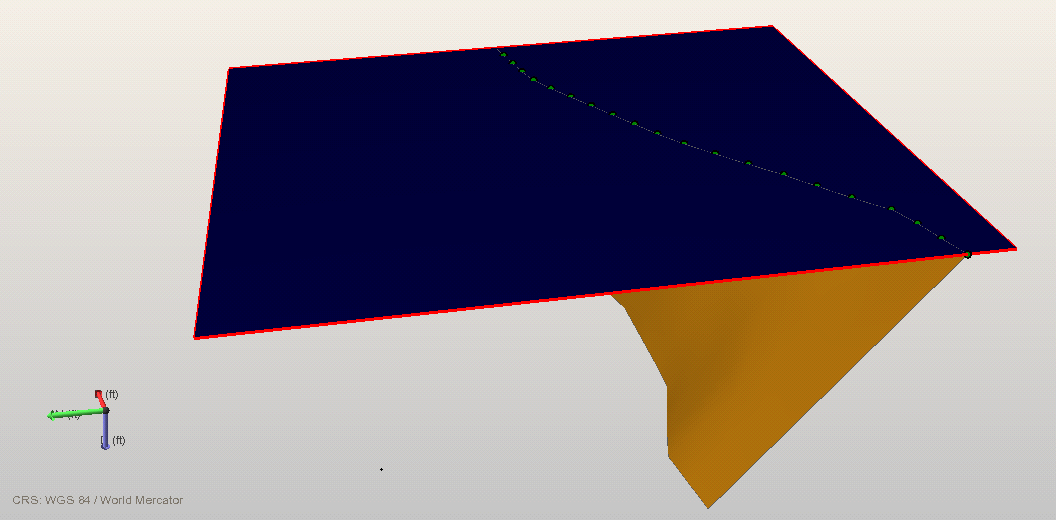
Example 1: successful validation. The unconformity (in blue) truncates a fault (in orange). The red unconformity boundary indicates there is no offset (the red boundary encircles the complete unconformity); this intersection can be validated click to enlarge
Example 2: successful validation. The unconformity (in blue) is intersected by a fault (in orange). The red unconformity boundary indicates that the unconformity is not offset by the fault (the boundary encircles the complete unconformity). This intersection can be validated click to enlarge
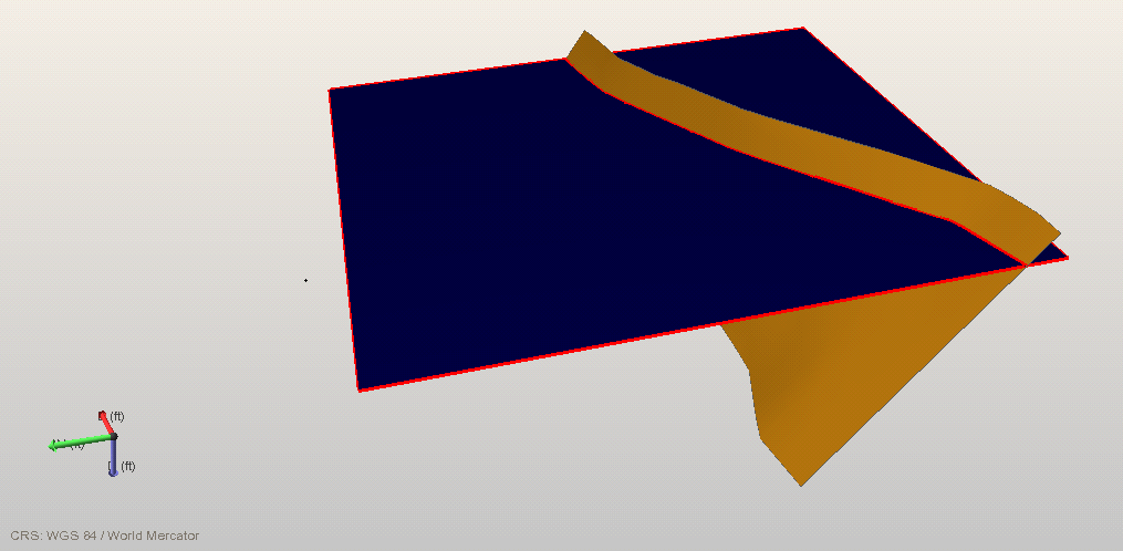
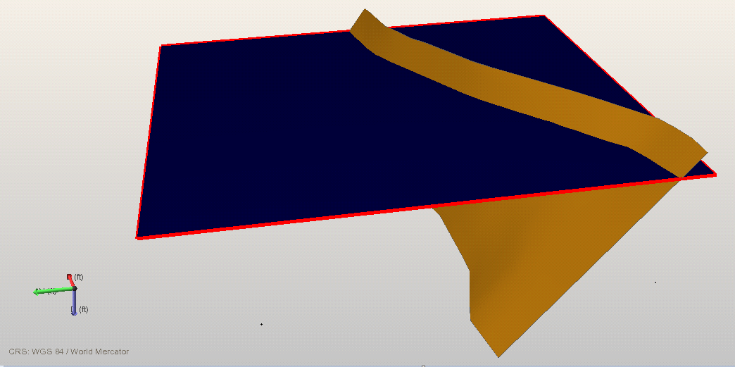
Example 3: non-successful validation. The unconformity (in blue) is intersected by a fault (in orange). The red boundary indicates that the unconformity is split into two pieces (the red boundary follows the fault gap) which means it is offset by the fault. This intersection cannot be validated click to enlarge
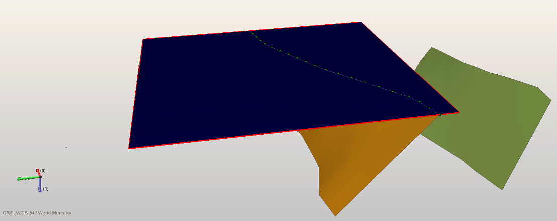
Example 4: non-successful validation. Same situation as example 1, except for the presence of the green fault. The reason this case cannot be validated is the fact that the green fault is located closer to the unconformity than two times the 'lateral modeling parameter distance', when the unconformity has been extrapolated field-wide (unconformities in fault models always need to be field-wide); during gridding the nearby green fault might offset the unconformity. click to enlarge